The positioning of the paper in one plane must be carried out in two directions: the positioning of the paper in the forward direction to ensure accurate positioning of the paper up and down; the positioning of the vertical paper in the forward direction to ensure accurate positioning of the paper on the left and right.
In the actual printing process, the single sheet of paper first reaches the front gauge. After the front gauge is at rest, it is pulled or pushed toward the side gauge. The front gauge positions the paper in the forward direction (circumferential direction), and the side gauge positions the paper in the lateral direction (axial direction). Generally, the front gauge of the machine is at least two, most of the machines are equipped with four, but in fact only two are used for positioning, this is because two points determine a straight line, the front gauge is less than two, if more than When the two are not adjusted properly, the positioning action sometimes interferes with each other. The side positioning makes the paper have an additional positioning point, which can be seen: the positioning principle of the ruled part actually uses the geometric principle of two points and one line, and three points and one side.
Front rule
The main functions of the pre-regulation are as follows:
(1) Positioning the paper circumferentially The circumferential positioning of the paper directly determines the accuracy of the overprint in this direction.
(2) Change the size of the gripper During the printing process, sometimes it is necessary to change the size of the gripper. There are generally three ways to solve this problem, one is to borrow the plate cylinder; the other is to pull the plate; there is another It is to adjust the front and back position of the front gauge. When the amount of change in the mouth is relatively small, it is convenient to move the front gauge, but generally, move the front gauge as little as possible.
(3) Make up for the error of plate-making and plate-making. Plate-making and plate-making are sometimes difficult to ensure that all the images are in the standard position, so it is necessary to achieve the determined position through the micro-adjustment of the previous regulations.
(4) Make up for the error of paper feeding In the process of paper feeding, the paper enters a semi-constrained state from the free state. It can be said that the paper that arrives at the front gauge every time is not necessarily in the same position, but the paper arrival is determined by the positioning time at the front gauge s position.
(5) Create conditions for side positioning The side positioning is based on the previous position.
The front gauge is generally divided into two types: the upper swing type and the lower swing type (this is classified according to the upper and lower swing center). The upper swing type front gauge is very convenient to adjust and install. The lower swing type front gauge can not leave the paper completely It can return to the side of the iron table when feeding paperboard, which increases the positioning time of the front gauge, which is easy to ensure the positioning accuracy. Under the condition of the same positioning time, the speed of the machine can be increased, so the upper swing type front gauge is suitable For low-speed large-format or high-speed small-format paper, the swing-down front gauge is suitable for high-speed large-format paper.
Most domestic offset presses use a combination of swinging front rules,
Figure 4-1 The structure and working principle of J2108 front gauge
As shown in Figure 4-1: the working position of the front rule depends on the coupling position of the cam 1 and the eccentric bearing transmission gear of the paper delivery tooth swing shaft, that is, the machine is at the "0" point (J2108, J2205 models specify the impression cylinder When the gripper starts to grip the paper at the "0" point of the host, the "0" score line of the cam 1 comes into contact with the roller. Since the position of the cam has been accurately adjusted by the manufacturer, it is fixed with pins, and it is generally no longer adjusted during use. If the paper is found to be improper at the time of overhauling the machine, then the cam 1 can be borrowed.
The most common adjustment of the front gauge is the front-rear and height-adjustment of the paper blocking positioning plate 17. The front-rear adjustment is used to adjust the front gauge when it is inconvenient to make a small amount of circumferential adjustment for printing or to pull the printing plate. Loosen the lock nut 19 and turn the adjusting screw 18 to move the positioning plate 17 forward and backward, and then lock the nut 19 after adjustment. [next]
According to the thickness of the paper, the height of the positioning plate can be adjusted appropriately. In general, when the front gauge is in the positioning position, the gap between the bottom surface of the curved surface of the positioning plate and the plane of the iron table should be three times the thickness of the printed paper. For individual adjustment, first loosen the screw 16 that fixes the front gauge seat frame, hold the front gauge by hand to adjust its height, and then tighten the fixing screw 16 after adjustment. If the overall adjustment is possible, first loosen the lock nut 24, then turn the adjustment nut 20, change the height of the connecting rod 7, deflect the front gauge shaft 13 by an angle, and drive the positioning plate up or down. There should be a gap of 0.1 mm between the adjusting nut 20 and the sliding sleeve 4 at the previous specified position to ensure that the eccentric pin shaft 22 and the rod 8 are tight. The gap can not be large, too large will increase the positioning time.
The gap between the front plate and the iron table is generally three times the thickness of the printed paper (if the paper thickness is greater than 0.3 mm, the gap is the paper thickness plus 0.2 mm). A contact reed (Figure 4-1) is installed at the upper gauge of the front gauge of the domestic offset press. It is usually called an electric tooth. It is used to detect the condition of the paper reaching the front gauge. The film and the power supply, at this time, the power supply is turned on, and the paper feed immediately stops working.
This type of detection device is also installed on the multi-color offset printing machine, commonly known as the electric eye, such as the front gauge electric eye of the CD102 machine. Place the paper on the front gauge when detecting paper. If the paper contacts the front gauge in the correct position, the two control information Both black blocks) will appear on the display (Figure 4-2). Conversely, if there is only one control message or no control message at all, the paper needs to be adjusted to the electrical eye.
(Figure 4-2) Front (side) gauge electric eye detection
.Adjustment of the front eye:
.a If the display has no control signal (black square).
b. Slowly turn the knob clockwise (Figure 4-2 / ​​①) until the first control signal appears.
[next]
Figure 4-3 Adjusting the front gauge electric eye
c Continue to turn the knob slowly clockwise (Figure 4-2 / ​​②), indicating that the paper reaches the front regulations of the transmission surface and the operation surface at the same time until the second control signal appears.
[Expert Tip]: It is generally best to have two control signals appear at the same time, or the second one should not appear later than the first signal by 5 divisions. If this is not the case, then the paper may fail before reaching the gauge.
d Mark the position of the lower knob (Figure 4-3 / â‘ ), and then continue to turn clockwise for two more times.
e Remove the paper and both control signals disappear.
[Case 4-1]
A factory has a J2205 offset printing machine. It has been used for about five years. At one stage, the upper and lower rules are always curved, either the upper half line or the upper half line. The rules are good and bad. And the mechanical parts related to the front gauge have been adjusted many times, and they have not worked. Later, after careful analysis and research, it is recommended to remove the front gauge. It is found that the front gauge has different grooves in the front board. The slot made the upper and lower rules better and worse. Later, two new front rules were replaced and the fault disappeared.
[Expert Tips]:
Regardless of whether it is a domestic or imported offset press, the front gauge cardboard is impacted by thousands of different thicknesses of paper, and it will inevitably leave a groove at the front gauge cardboard. New pre-regulations, otherwise, up and down regulations will be good and bad.
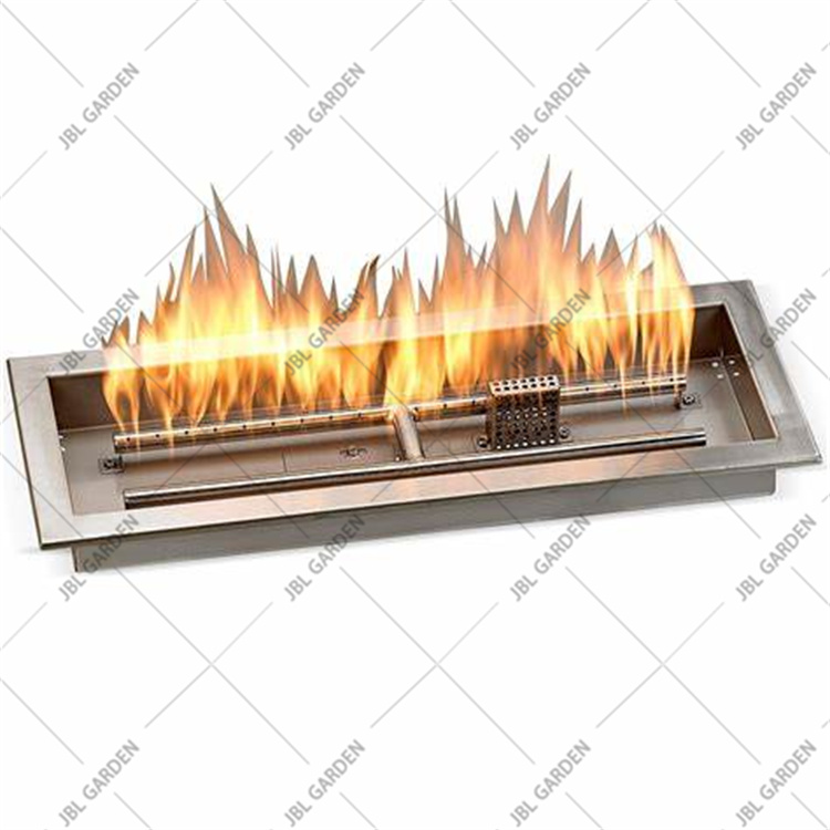
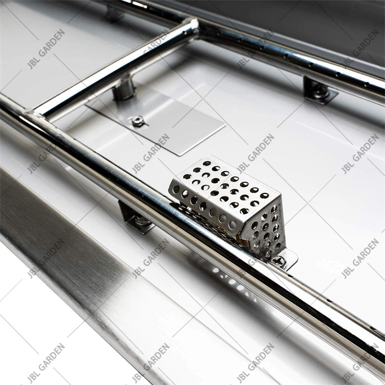
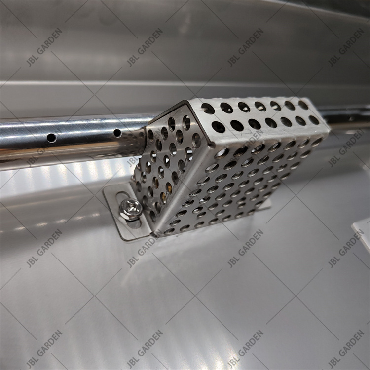
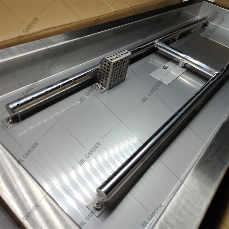
Traditional style low-rise table-top Fire Pit pan. Its size (980mm by 370 mm) and weight make this fire pit bowl easily transportable for camping, fishing or a simple barbecue. Because of its compact size, it's also convenient for use on balconies of small terraces.The fire pit pans & burners are made of 304 stainless steel. Designed to withstand extreme heat & harsh weather without damage or rust. Creates a brilliant, uniform flame. Add fire glass or lava rocks to match your decor to complete the look.
| Name |
Stainless Steel Propane Fire Pit Burner |
| Material | Stainless steel |
| Size | 800*800mm |
| Steel thickness | 2mm |
| Weight | 3.5KG |
| Packing | carton |
Packing
Packing will by carton and pallet
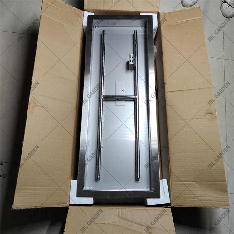
Rectangle Fire Pit Burner,Fire Pit Insert Rectangle,Rectangle Log Burner,Rectangle Burner
Henan Jinbailai Industrial Co.,Ltd , https://www.jblbbqgrill.com