The writer is an experienced power engineer who uses an oscilloscope in the field for a long time. In this capacity, he proposed to pay attention to some details in the process of using the oscilloscope, including: self-calibration of the oscilloscope before use to compensate the probe; limit the bandwidth when measuring the power supply ripple, remove the probe "hat" and ground wire Clip; the passive probe cannot be used at the same time when measuring the original and secondary sides of the power supply. The article on power supply ripple measurement also talks about shunt capacitance at the front end of the probe, but lacks an explanation for the rationality of this approach. It is worth noting that with regard to ripple measurement, there is no emphasis on reducing the range smaller, but the oscilloscope range should be as small as possible, which should be the first principle to measure the power supply ripple.
I have been in the power industry for 5-6 years, and the oscilloscope is equivalent to my right hand. Without it, I can't do anything. The existence of it allows me to successfully complete many project design and problem analysis. For me, today, its credit is irreplaceable. For the power supply engineer, once there is a problem with the product, it is necessary to grasp the waveform, grasp the timing, and test the accurate value to help the engineer analyze and process. Speak with the facts and watch the waveforms. How to make the test data accurate and reliable is very important. Accurate numbers can help us, and the distorted waveforms and values ​​can only mislead us, let us run the opposite direction, let us lose our direction and do more work.
Think about it carefully. Although I am not as proficient in oscilloscope research, I have read many articles about oscilloscopes. I have encountered many problems in practice and solved many problems. I still have a little experience to share with you. I hope that everyone can help. If you write badly, please forgive me.
I often see that many small companies use oscilloscopes that are too low-end, have low bandwidth, and have a low sampling rate. They think that they can capture waveforms. They don't think it is necessary to buy such a good oscilloscope. They think that oscilloscopes are easy to operate and there are not so many specifications. Seeing their operation on the oscilloscope, do not prepare for the test, use it up, in fact, it is not correct, it may often be that this operation is not correct, resulting in distortion of the test results, affecting the analysis. Even some very experienced engineers may not notice some details. Many engineers lack understanding of the oscilloscope, and how to better use the oscilloscope still needs to be improved. Here are some of the problems that many engineers I have seen to correct and share some of the knowledge I have.
1. Many engineers take the probe directly to test, do not check whether the probe needs compensation, and whether the oscilloscope needs to be verified. Only in some large companies or trained engineers will be prepared before use.
The oscilloscope requires self-calibration and requires probe compensation adjustment before use. This adjustment is performed to match the probe to the input channel.
When operating the instrument for the first time and simultaneously displaying data from multiple input channels, it may be necessary to calibrate the data vertically and horizontally to synchronize the time base, amplitude, and position. For example, calibration is required when significant temperature changes (> 5°) occur.
1. Disconnect any probes or cables from the channel input connector. Make sure the instrument is running and warming up for a while. In the R File menu, select Selfalignment.
2. On the Control tab, click Start Alignment.
3. In the R alignment state field. The results of each calibration step for each input channel are displayed in the Results tab.
The steps for adjusting the probe compensation are as follows: 1. Connect the oscilloscope probe to the channel and press the PRESET button on the front panel (in the left panel setup area). Connect the probe signal end and ground reference to the reference output on the oscilloscope panel and press Autoset. If using a probe hook front attachment, securely attach the front end of the signal pin to the probe to ensure proper connection. As shown in Figure 1:
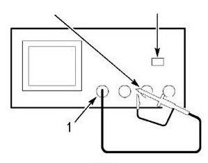
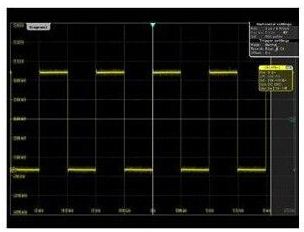
Group 1 probe compensation adjustment
2. Check the shape of the displayed waveform. The situation that may occur is shown in Figure 2.
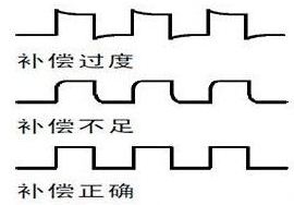
Figure 2: Overcompensation, deficiency and correct compensation
Over and under need to adjust the probe. In order to better test the exact value.
3. If the waveform is not correct, adjust the probe. As shown in Figure 3 below, until the waveform is the correct compensation waveform above.
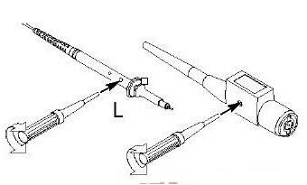
Figure 3 compensation probe method
The above two points seem simple, but they are often ignored by engineers. In order to make the measurement more accurate, please pay attention to the inspection. These two calibration functions should be available on any oscilloscope.
2 test voltage ripple
Many power supply engineers don't pay much attention to the ripple measurement, taking it for granted. The use of oscilloscopes varies widely, resulting in very different test results. As shown in the following figure 4 and group 5, for the same test point of the same product, the test results vary greatly due to the difference in test methods. Ripple is an important parameter for the power supply, but it is not worthwhile to make a test failure due to its own operation problems, and waste a lot of manpower and cost to rectify.
Sometimes your customers have incorrect data for testing due to insufficient use and attention to the instrument. However, there is no problem with the products on your own. It doesn't make sense to say how much, so that customers think they are cheating them, so the test method is very important. Paying attention to these details can save you a lot of time and take your abilities to the next level.
The value of the oscilloscope test itself is inaccurate (I will not explain it here). Many companies now require the value of the test waveform as the basis for the decision. In fact, the oscilloscope is only a process of testing the voltage over time, mainly to capture the waveform during debugging. The accuracy of the specific measurement of the DC voltage RMS is not as good as the value of the digital multimeter. The calibration of the oscilloscope's DC accuracy is also based on a multimeter. But more and more companies and engineers use the value of the oscilloscope as the true value, then we can only try our best to make the test error the least.
The following is a graphical and analytical analysis of the test ripple:
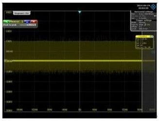
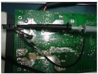
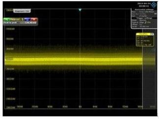
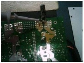
The result of the test ripple of the four groups of the four groups of Figure 4 is 3.921V, which is much larger than the figure of 0.126V, but the test value of the group diagram 4 is not true. Analysis of the problem: In fact, there is no problem with the product. There are only problems with the test method. Now let's point out the problem:
The first error was the use of a long ground wire.
The second error is to place the loop and ground wire formed by the probe near the power transformer and switching components.
The third error is the extra inductance between the oscilloscope probe and the output capacitor.
Because of these inadvertent, many high-frequency signals, the magnetic field of the transformer, and the electric field of the switch are picked up, so that the waveform captured by the oscilloscope is displayed with high-frequency noise doping.
The fourth error is that the range is too large.
Accurately testing ripple requires:
Use bandwidth limits to measure ripple to prevent picking up high frequency noise that is not really present. The oscilloscope bandwidth can be set to 20M. Remove the probe "hat" and ground clamp to prevent the antenna effect of long ground lines. Wrap the ground wire between the probe and the ground. Rohde & Schwarz has a short line of special equipment. Consider decoupling a 0.1uf and a 10uf capacitor in parallel between the signal and ground. The length of the PIN pin of the capacitor also affects the value of the test.
3 Because many engineers do not understand the oscilloscope, resulting in misoperation, after damaging the oscilloscope or power supply, it is still unclear why
Many junior engineers use a multi-probe to measure the power supply. As soon as the power is turned on, the power supply product "explodes" and even damages the oscilloscope. They will ask me, is the oscilloscope not directly connecting the probe between the components to be tested? I don't seem to be wrong. Why is this? It is because I don't understand the channel and ground connection of the oscilloscope. Multiple probes of the oscilloscope are common across the oscilloscope. Therefore, when measuring the primary side and the secondary side of the power supply at the same time, if one probe is used to connect the ground of the primary side, and the other probe is connected to the ground of the secondary side, the ground of the internal passage of the oscilloscope is connected, which is equivalent to the power supply. The ground of the primary side and the secondary side are short-circuited together. However, there is a voltage difference between the primary side and the secondary side. Therefore, the large current after the short circuit easily burns the product and the probe, and may even damage the oscilloscope. When testing the primary and secondary voltages, use a differential probe on one side and a normal probe on one side. Even if the same side line is tested, the ground of the probe is a common reference point. The ground of the oscilloscope is connected through the power ground. Many companies basically add an isolation transformer in front of the oscilloscope. This method is quite good. Some companies directly cut the PIN pin of the three-phase ground of the power supply, so that there is no grounding, and the leakage current will increase when the oscilloscope casing is touched by hand. It is not recommended to use this.
In fact, the problem is not only these, such as the application of dynamics, the application of calculation between probes, and the consideration of test voltage values. Everyone knows that the function of the oscilloscope is very powerful. There are almost no electronic engineers who do not use the oscilloscope. Therefore, when you use the oscilloscope, you must think about it more, experiment more, understand the function of the oscilloscope, and understand the difference between the internal option keys. The impact of oscilloscope parameters on the measurement will help us better. Don't just do it for the task. Seriously start and carefully observe, so that our progress will be great. Experience is accumulated step by step.
- This tufted armchair features comfortable and extraordinary sturdy with 19.5" high backrest and 46" large cushioned recliner bed which can bear up to 500 lbs, provides comfy sit on for extended periods
- Side curved rolled tufted armrest meets contemporary clean lines, streamlined design, and modern comfort, perfect for placing your book/magazine / Laptop when you lie - down
- Leather covering material which is easy to clean.
Leather Chaise Lounges,Chaise Lounge,Chaise Lounge Chairs,Chaise Lounge Sofa
Kaifeng Lanwei Smart Home Co., Ltd , https://www.manualrecliner.com