With the development of modern computer technology, programmable controllers have made great progress. In 1968, for the leap-forward development of its own auto industry, gm, the largest American car manufacturer, proposed that the new generation of controllers should have ten conditions. This has become the development trend of contemporary programmable controllers. In 1969, the United States Digital Equipment Corporation (dec) successfully developed the world's first programmable controller pdp-14, and was used for the first time on the auto assembly line of gm company with success.
PCC function module structure and its characteristics
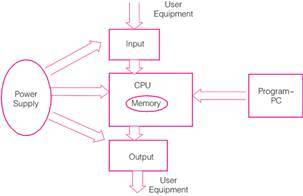
PCC is a computer control system with a central processing unit (cpu), input / output (i / o) interface, power supply, etc. Its structure is shown in Figure 1. pcc realizes a series, modular and standardized design, which makes it easier to design and install, short debugging period, simple maintenance, etc. All its input and output interface circuits are optically isolated, which can effectively inhibit external interference sources from pcc Impact. In addition, the pcc module has a rich variety, complete communication interface, simple configuration, and can be easily networked for communication. Modern PCC has evolved from smaller-scale stand-alone sequential control to include process control, motion control, step control, etc., and is widely used in many industries such as plastics, packaging, printing, paper, etc. These applications have greatly improved Industry productivity and product quality.
For program execution, pcc uses a time-sharing multitasking operating system, which can implement multitasking well, and users can compile their own programs and set the cycle time according to their own production needs. The control system provides users with eight task levels with different cycle times and different priority levels. At the same time, it is a customizable and deterministic implementation of a multitasking operating system. At the same time, in order to be able to provide more services to technicians and programmers, and facilitate users to get their own data and control system status, the pcc programming system provides users with many different diagnostic tools. These tools can display a running summary, can read, store, and modify information, and can drill down into the system and optimize it.

Figure 1 pcc module functional structure
B & R 2000 series pcc
b & r2000 series pcc has 2003 series and 2005 series. Including: CPU module, bus controller module, communication module, power supply module, field bus module, digital, analog input, output module counting and positioning module, etc. b & r2000 series pcc hardware has the following characteristics [2]: ①hardware modularization; ② network communication capability; ③ has interface with hmi communication; ④ has industrial juice computing capability; ⑤ emc conforms to en61131-2; ⑥ reliable i / o bus Protocol; ⑦Independent i / o bus and system bus ⑧Industrial-strength terminal block; ⑨Multi-i / o bus system with high performance.

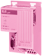
Figure 2 2003 series pcc
(1) 2003 series of small pcc (see Figure 2)
The 2003 series is a small PCC, and its characteristics are: the 2003 series adopts a compact design with extremely high cost performance, which saves the space of the equipment; the CAN bus network realizes the direct connection of the operation panel, display unit, drive and other peripheral equipment; remote i The / o system realizes the possibility of remote control by can; a large number of screw-in modules also ensure the connection of any sensor and actuator signals; realize distributed or integrated units in the machine or system, and the trunk communication between the units passes the standard Ethernet tco / ip network or field bus is implemented. In each unit, the 2003 series can be expanded by driving the operation panel and peripheral devices. The appropriate CPU module is selected according to the computing power required by the machine unit; the compact control of the 2003 series The controller is also suitable for large-scale systems. If a CPU with local i / o is connected to various distributed components through ethernet powerlink, a high dynamic motion task can be created
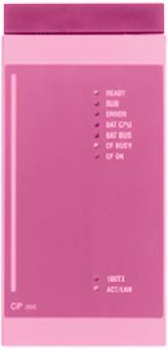
(2) 2005 series of medium-sized pcc (see Figure 3)
The 2005 series is a medium-sized pcc, which is a high-performance programmable computer controller (pcc) produced by B & R. It not only has the characteristics of the 2003 series, but also has the following advantages: supports embedded pc-based technology, and With strong analysis and calculation capabilities, the huge bandwidth of its peripheral signal input and output can meet all the requirements of machinery manufacturing, factory automation and process automation, and cooperate with other B & R products, such as i / o systems, industrial pc and Controllers, etc., can create automation solutions that meet the highest requirements; relying on advanced interfaces, fieldbus systems, networks, and peripheral equipment to complete the best data transmission tasks; the latest 2005 series is based on Intel-compatible processors and has the most advanced Framework, creative PC technology such as compact flash storage, Ethernet connection and apci expansion slot, etc. make high-performance products in the IT world also applicable in the field of automation; programming uses a fully compatible, unified format b & r automationstudiotm; , 2005 series of i / o modules can realize remote operation, the bus controller has got rid of location restrictions, and makes the connection Sub closer machine, data is transmitted through the ethernet powerlink Distributed System Security highest performance.
The 2005 module is installed on the bottom plate, and the bottom plate is installed on the guide rail in the power distribution cabinet. The connection of the sensor and actuator signals are pre-configured on the plug-in terminal block, which also minimizes the work in the power distribution cabinet. The 2005 series power supplies are also installed on the base plate, and there are various power supply voltage values ​​to choose from. Each logically independent machine unit or product unit is equipped with an independent controller for controlling local drives and i / o systems. The configuration, programming, and testing of these independent units are performed before shipment. Can be easily completed, the communication between the units that do not require high time and the operations between them even the display site and the factory network can be built on Ethernet tcp / ip and opc.

Figure 3 2005 series pcc
pcc programming system
1 programming language
As we all know, the traditional industrial programmable controller programming language is the ladder diagram. Like most programmable controllers, pcc also uses simple and intuitive control-oriented statements oriented to the control process and problems, directly expressing the actions of the controlled object The input-output relationship directly expresses the actions of the controlled object and the input-output relationship. Common programming languages ​​include: ladder diagram lad (ladder diagram), instruction list il (instruction list), structured text st (structured text), sequential function chart sfc (sequential function chart), b & r automation studio, and standard c language (ansic ), Etc., where the ladder diagram lad and instruction list il (instruction list) language is still very popular in the use of pcc, while b & r automation studio and standard c language (ansic) have been more and more widely used due to their powerful functions. application.
2 Development environment
The current B & R programming software is automation studio. Figure 4 shows the user world of programming software. The automation studiotm user interface includes the following:
Main menu: The main menu of b & r automation studiotm can enter all functions.
Toolbar: The buttons in the toolbar can quickly run multiple commands and functions.
Work area: displayed here when the project is opened, and the project window can be adjusted to the largest or appropriate window size.
Information form: The information form is located below the programming form and displays compilation information, debugging information, etc. In addition, the results of the search function "find in files" are also displayed.
Status bar: The status bar is located below the entire window and displays the following information: short help about menu commands or toolbar icons; brief information on compilation steps; online connection status of the programming device and target system; status data of the currently active window .
(1) Status bar (see Figure 5)
In automation studio, the status bar is at the bottom of the window. The following information is displayed at the bottom right of the form:
a.offline (offline)-not connected to the target system
b. The target system connected to
c. cpu type + operating system version on the controller
d. Controller status.
Figure 5 Status bar
(2) Error logbook
The operating system records all fatal errors, warnings, and messages that occur in the application. These errors are stored in the system's error logbook and can be browsed through the project window. The error logbook can also be saved as a file. The error log is located in the memory of the controller and can be uploaded from the memory. Select the log book tab in the software window to open the error log.
(3) Watch window (watch)
The primary purpose of the monitoring window is to observe and modify the variables of the controller. In addition to variable values, other important information (data type, range, i / o data points, etc.) can also be displayed. Variables are managed in the form of lists, and different configurations (variable groups) can also be stored. By clicking insert variable in the shortcut menu, you can add the variable of the selected task in the watch window. In the monitoring window, the red light indicates the output variable, and the green light indicates the input variable. Double-click the variable value box will pop up a mandatory option form, after confirmation, you can force change the value of the variable. When the forced state is turned on, the system will write the value entered in the monitoring window to software or hardware, regardless of the state value of the i / o data point. Monitoring can be used to obtain information about the target system.
(4) Trajectory tracking
When testing variables, because some variables change too fast, the watch window cannot keep up with their changes. Because the changes of these variables are random, it is difficult to tell them exactly, so there is a tracer. This tool can report changes in variable values ​​over time and display them in the form of a graph. The graph results can be stored for later observation and processing. When system monitoring starts, you can open it by clicking trace under the shortcut menu.
(5) Debugger
The debugger can catch software errors hidden in the text programming language. By setting a breakpoint in the source program, the program stops execution at the line of code where the breakpoint is set. This can determine the direct relationship between the variable value and the currently executed program line. When you want to know more about the running program, you can use the step into (step) and step over (skip) function keys to complete this program segment.
(6) profiler
The profiler tool can measure and display important system files, such as: task running time; stack utilization; system utilization, etc. According to system utilization (load) to analyze the system running time, this information can help users how to use resources to optimize the system.
(7) pvi transmission tool
The pvi transmission tool is a versatile diagnostic and service tool. It is not only limited to the transmission project, but also combines several different diagnostic functions and can choose to install the pvi transmission tool when installing pvi runtime & server. Enter the tools menu in automation studiotm and select pvi transfer tool to start the pvi transfer tool. If automation studiotm is not installed, you can also start it directly from the menu under windows start [6].
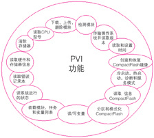
Figure 6 is a functional diagram provided by the pvi transmission tool.

Figure 6 pvi functional composition
As the development trend of modern industrial control technology, programmable computer controller pcc combines the advantages and high performance of traditional industrial control systems. It has a friendly programming platform, a wide range of programming languages, and programming is easy to learn. The wide variety of pcc modules, serialized, modular and standardized design make it easy to apply, good versatility, powerful CPU with high-speed processing capability, advanced operating system, high reliability and anti-interference ability. The implementation of a multitasking system makes the control process more flexible. Competent for large-scale distributed control, complex process control and high-precision motion control, it can complete field control tasks of various sizes, and has a very broad application prospect. (Zhang Zhilong)
We are a professional manufacturer of makeup brushes for 17 years. We accept all OEM ODM makeup brushes set for you We can customize the color count and shape of the makeup brushes. The logo can also be customized. There are also Makeup Brush sets available for sale.Meet all your needs for makeup brush sets
Makeup Brush Set Eyes,Makeup Brush Set Sale,Makeup Brush Set Face,Makeup Brush Set On Sale
Shenzhen Nanfang Shishang Cosmetic Utensil Co., Ltd. , https://www.nfbrush.com